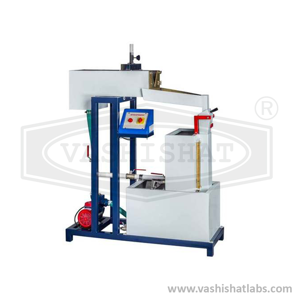
In this setup, water is delivered from the bottom of a long and wide conduit, designed for the lab experiment. At one end of the channel, a notch is installed. The height of the fluid in the flow channel is measured using a hook gauge with a Vernier scale. A plan is created to allow for interchangeable notches. The setup includes three rectangular brass notches as part of the set, which includes a 45° V notch and a 60° V notch. The system also features a self-contained water recirculation unit, including a sump tank, a centrifugal pump, and other components. The water pipe has a flow control valve and a bypass valve, allowing for experiments with different flow rates. The water flow rate is measured using a measuring tank and stopwatch.
Experimental Objective
• Determine the coefficient of discharge (Cd) for 45° V-notch, 60° V-notch, and rectangular notch.
• Observe and study water discharge over different types of notches.
• Analyze how discharge varies with notch type and geometry.
Specifications
• Channel Test Section: Size 600 × 250 × 180 mm.
• Notches Included: Rectangular notch, 45° V-notch, 60° V-notch, trapezoidal notch, and three brass notches in total.
• Measurement: Hook or pointer gauge with Vernier scale for accurate fluid height measurement.
• Water Circulation: FHP pump (Crompton or Sharp) for reliable operation.
• Flow Measurement: 25-liter measuring tank with piezometer.
• Sump Tank: 70-liter capacity for water storage.
• Timing: Electronic stopwatch for precise time measurement.
• Control Panel: Equipped with on/off switches, main indicator, and standard controls.
• Construction: Entire setup is precisely engineered and built to high quality standards.
Utilities required other than above supply
Discharge Over Notches Apparatus