
The
device consists of three suspension elements (spring balances) with varying
stiffness, connected at a single point to form a redundant joint. The upper
ends of the suspension members are attached to a vertical wooden board. A
vertical load can be applied to the joint, allowing for the measurement of its
horizontal and vertical displacement on paper. Dial gauges are used to measure
the elongations and forces in the suspension members. The device includes dial
gauges with magnetic bases for precise measurement.
Experimental Objective
Comparison
of experimental and theoretical results of forces in the members and the
component displacement of the loaded joint D of a three bar suspension system
for vertical loads.
Or
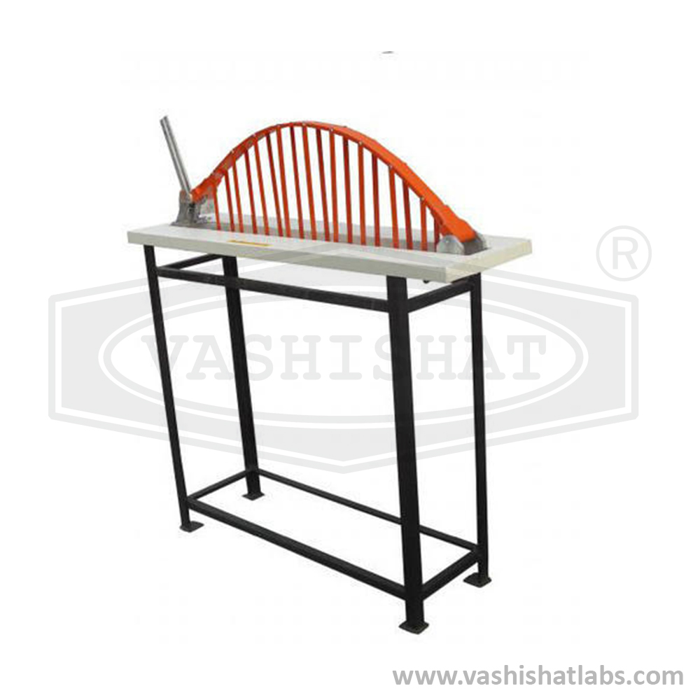
To study two hinged Arch for the horizontal displacement of the roller end for
a given system of loading and to compare the same with those obtained
analytically.
Specification
The
apparatus has a span of 100 cm and a rise of 25 cm. Both ends are hinged, with
one end free to move longitudinally. A lever arrangement is installed at this
free end to apply a known horizontal inward force, allowing for the measurement
of horizontal thrust. Various points along the horizontal span of the arch are
marked at equal distances for the application of load. This structure is
statically indeterminate of the first degree. The apparatus is supplied with a
dial gauge featuring 25 mm travel and a magnetic base. The mild steel apparatus
comes complete with a supporting stand and a set of weights.
Utilities required Other than above Supply
Redundant joint apparatus
dial gauge 1 no.
Magnetic base 1 no.
Hangers 1 nos.
Weight of 500gm as per requirement.