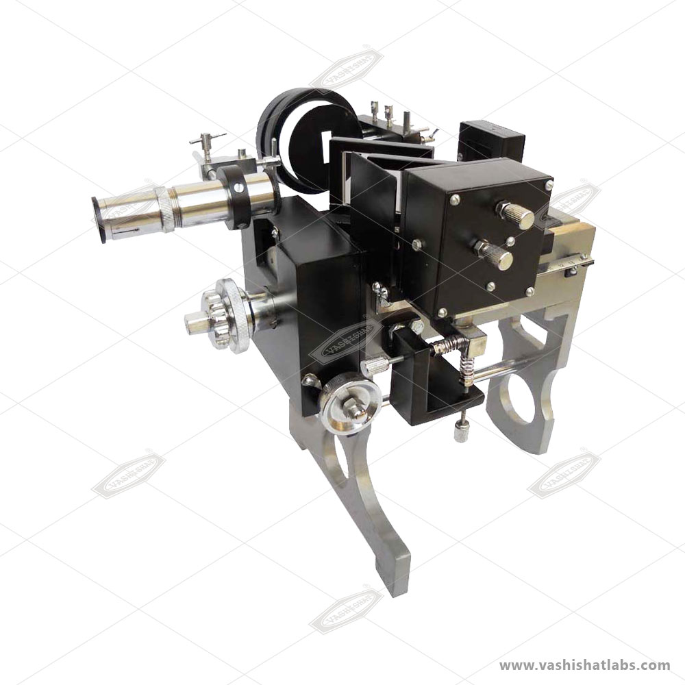

Michelson Interferometer is an instrument which is capable of producing interference fringes. This happens when a beam of monochromatic light is splitted in such a way that one beam falls on a fixed mirror and the other falls on a movable mirror. When these beams are reflected back and recombine at a particular point, interference happens and fringes are formed. This instrument is generally used to measure the wavelengths of different light sources very precisely. The measurement is done by creating interference fringes. It is generally seen while working on Michelson Interferometer that, the basic and initial settings are very hard and time consuming. Only a professional or experienced person can do all the preliminary settings of the instrument in order to view the fringes and begin the experiment. Keeping this problem into consideration, the Michelson Interferometer build by us is a highly refined and trouble free design. We have made some basic improvements and enhancements in order to make this instrument student friendly. Instead of 6 adjustment screws in the conventional design, our Michelson Interferometer is provided with only 2 adjustment screws at the back of the mirror M2. Mirror M1, beam splitter G1 & compensator G2 are factory adjusted and never to be tampered. With very less efforts and minor adjustments one can easily view the interference patterns by using our Michelson Interferometer . The instrument is designed in such a way that it can produce sharp and bright interference fringes of Sodium Light as well as of a Laser Light source. We employ one of the best & high quality optics in our Michelson Interferometers along with precise workmanship.
Supported on a stable metal stand. High quality front coated silver mirrors of ?/10 accuracy are employed. Mirror M1 & M2 (32mmx32mmx7mm). G1 & G2 (50mmx38mmx7mm) .All adjustments to locate the fringes are done by two knurled screws provided at the back of mirror M2. Top screw moves the mirror is the vertical plain and the side screw in the horizontal plain. Two more spring loaded screws under M2 are also provided for fine adjustments of fringes while removing parallax. Distance moved by mirror M1 is read on circular scale inside the front box (least count .01mm) and on micrometer scale on the right side of the box (least count .0001mm). A linear mm scale is also provided on the right side of the mirror M1 to position it properly. To determine the wave length of monochromatic light using sodium light source or Laser